Creating an Output from a MicroPlex
Drag Circuit Creation
With components placed in the workspace, click on an available pin and drag to connect it to the desired pin on another device.
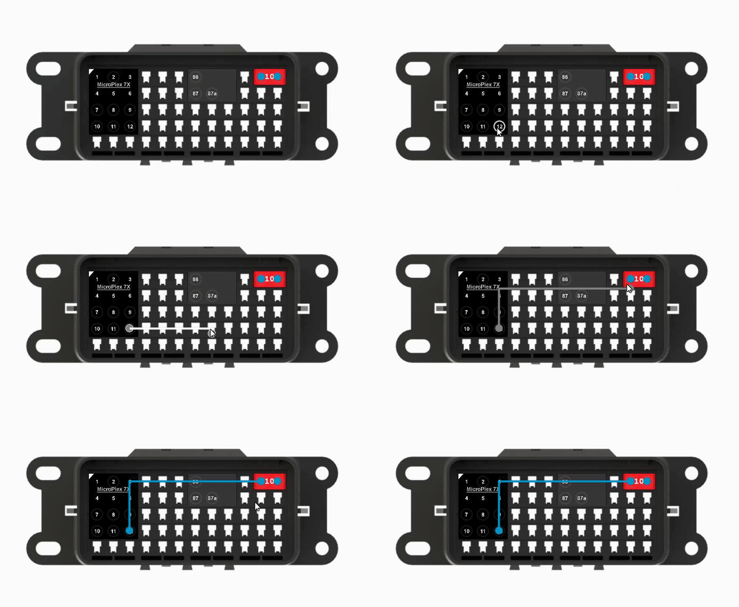
MicroPlex Lab now knows that there is a "wire" between the two pins in the box. The circuit created has no function at the moment besides electrically linking the two components.
Right Click Context Menu
When you right-click on a component in the workspace, you will be shown a context menu with options for the component. Some options are only available for MicroPlex controllers.
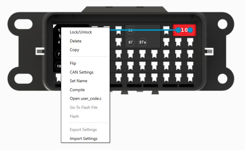
Lock/Unlock
Lock or unlock the selected component. Moving, deletion, and changes in logic for the component and its pins are disabled while it is locked.
Delete
Delete the selected component. If there is logic created on this component, you will be asked to confirm the deletion.
Copy
Copy the selected component. Right-click in an open area on the workspace to paste the component. You will be prompted to assign a name to the newly created component. When copying a MicroPlex controller, this feature will copy all of the data in the CAN Settings window from the original MicroPlex controller but will not save any triggers. If the space selected for the paste action does not have enough space for the component, it will not be pasted.
Flip
Rotate the component 180 degrees. Components cannot be rotated 90 degrees as the terminals in most fuse and relay boxes do not support this rotation.
CAN Settings
More information below
Set Name
Set a custom name for the selected controller. This is useful for referencing back to the compiled code from the controller later.
Compile
Take all user created triggers and custom code and send it to the remote compile server. You will get a response back from the server informing you if your compilation was sucessful or not. For every change made to the program for the controller, you will need to take this action to compile the new instructions for the controller.
Open user_code.c
The user_code.c file is the "backend" functional code of the controller. Advanced users can edit the raw backend code in this file to implement more complex logic.
Go To Flash File
Open the folder that contains the compiled file. This will allow you to backup or save compiled programs for use at a later time.
Flash
Open the built-in controller flash tool. This will select the most recently compiled program and attempt to find the controller via the MicroPlex Programmer or supported flash tools. Different flash tools can be selected globally in the settings pane of the application.
Export Settings
Similar to the Copy function, you can export the CAN Settings of the selected controller to a file for use later.
Import Settings
Import a previously exported settings file into the selected controller.
CAN Settings
The CAN Settings window is the main configuration section to control the CAN bus on MicroPlex controllers.
User Defined Messages
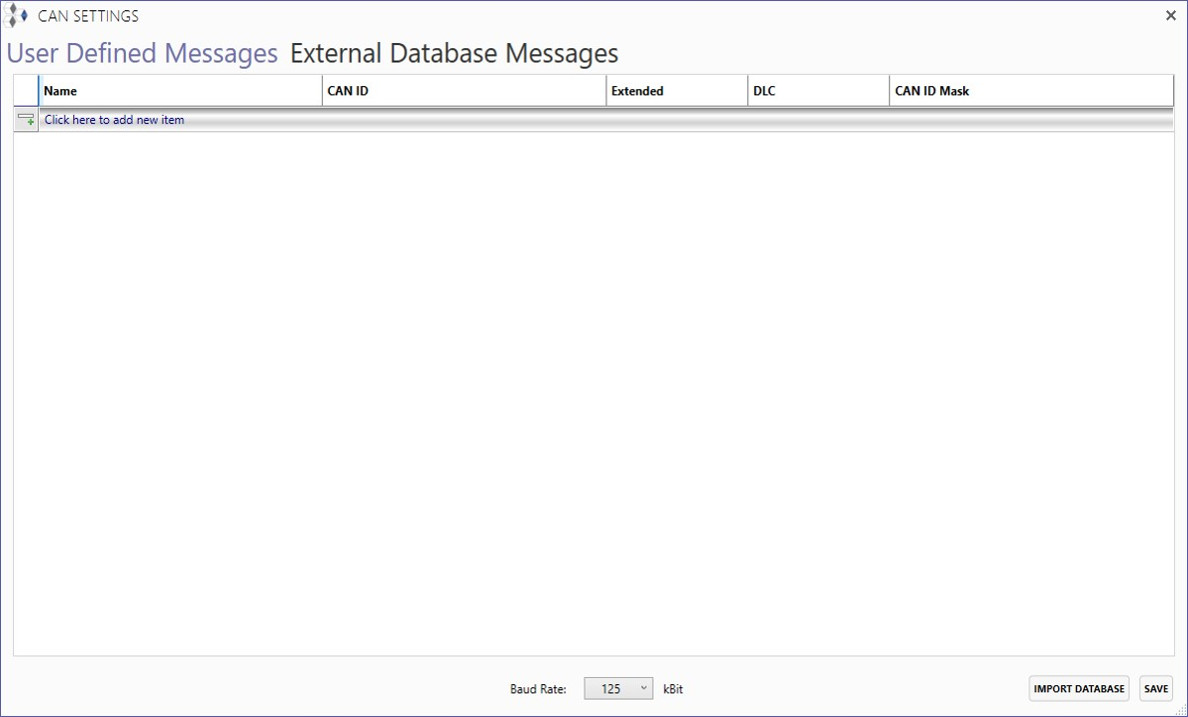
You can manually create CAN messages and the signals housed within, or import a PEAK .sym or Vector .dbc file. Make sure the .sym or .dbc file is properly formatted before importing. In addition, the baudrate of the controller can be selected here.
It is required for the controller to have signals inside the CAN Settings window before logic can be created graphically in MicroPlex Lab.
A demonstration .sym file can be downloaded here.
External Database Messages
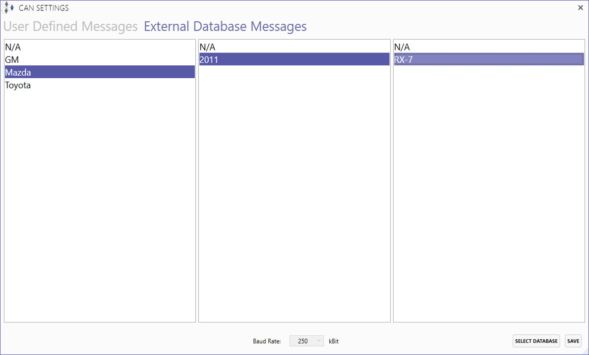
You also have access an online library of CAN databases. To use an external database, select the desired manufacturer, year, and model and then click the 'Select Database' button. The database's messages and signals will then be available to you in the Trigger Creation window.
Because databases are designed for a specific baudrate, the baudrate will be set to the correct value and locked while using an external database.
Trigger Creation
Once you have signals defined in the CAN Settings window, you can create triggers graphically for the circuits you create in the workspace.
Double-click on a circuit that involves a pin on a MicroPlex controller to open the Triggers window.
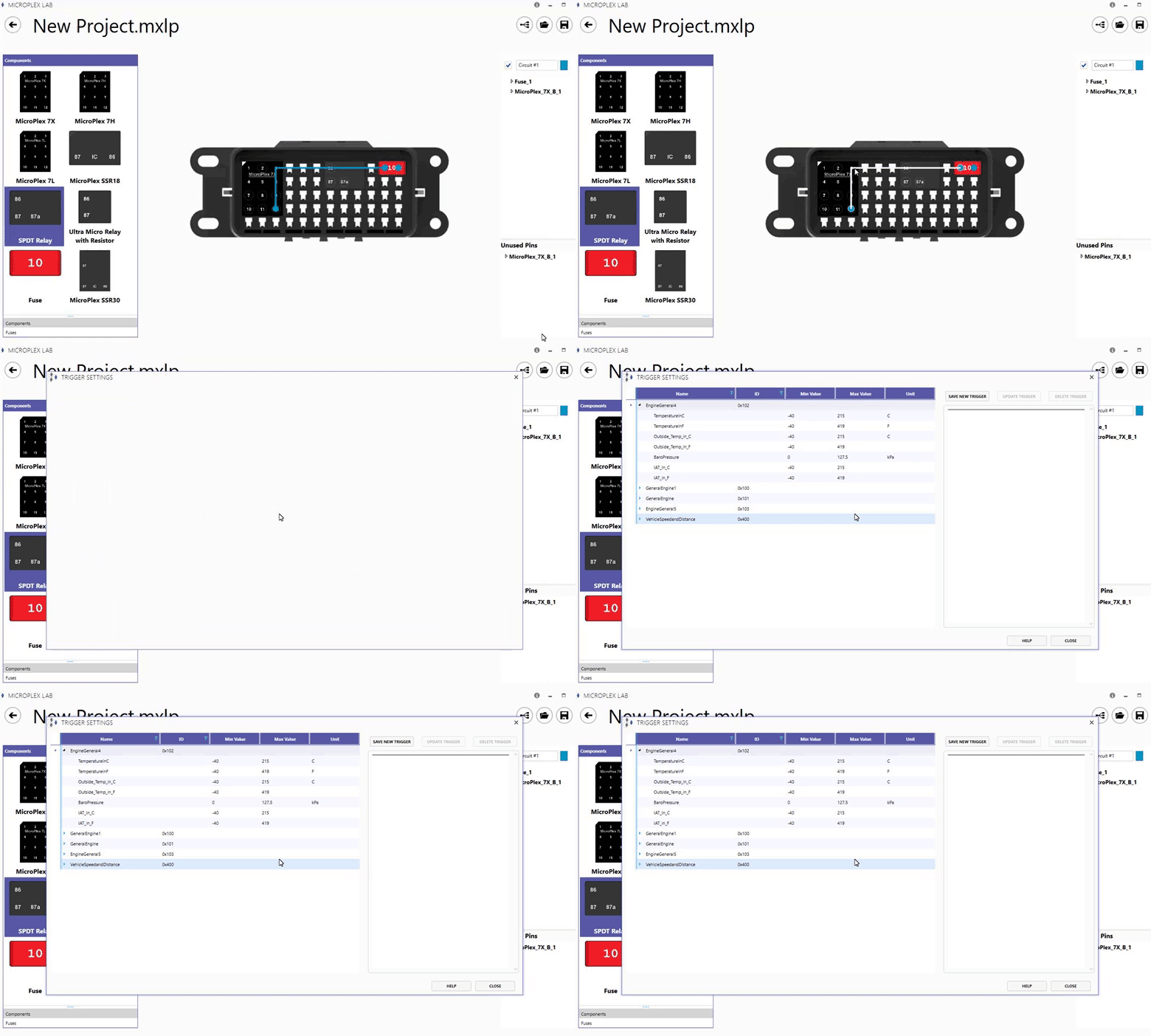
If a pin on a controller is in a circuit, its trigger window can also be opened by double-clicking the pin in the circuit menu on the right side of the workspace. In the trigger window, you will see the list of CAN messages and signals currently available to this controller. If using an external database, external CAN messages and signals will be identified with a green background.
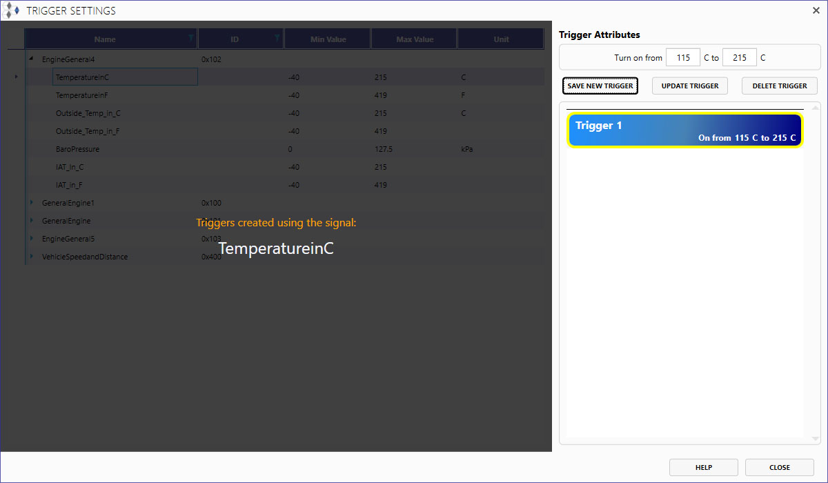
Triggers are currently only based on CAN messages. To create a trigger, select a signal and configure when the circuit will be ON based upon the signal.
With the example below, a trigger has been created using the "TemperatureinC" signal from the MicroPlex Demo .sym file. This means the signal is being monitored by the controller, which will turn the output pin in the circuit ON when the temperature signal is between 115 °C and 215 °C.
