Creating Circuits
Creating Circuits
Drag Circuit Creation
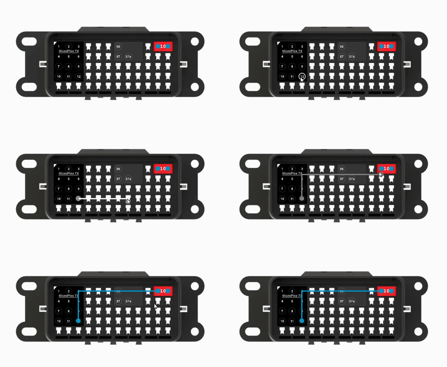
With components placed in the workspace, click on an available pin and drag to connect it to the desired pin on another device.

MicroPlex Lab now knows that there is a "wire" between the two pins in the box. The circuit created has no function at the moment besides electrically linking the two components.
Trigger Creation
Once you have signals defined in the Module Settings window, you can create triggers graphically for the circuits you create in the workspace.
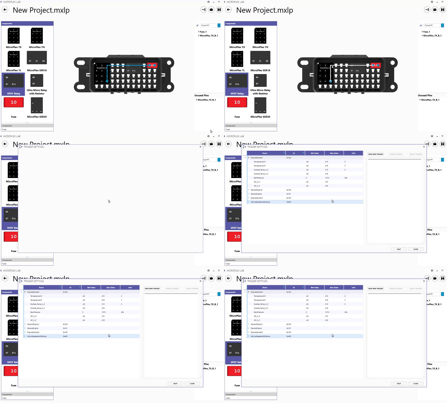
Double-click on a circuit that involves a pin on a MicroPlex controller to open the Triggers window.

If a pin on a controller is in a circuit, its trigger window can also be opened by double-clicking the pin in the circuit menu on the right side of the workspace. In the trigger window, you will see the list of CAN messages and signals currently available to this controller. If using an external database, external CAN messages and signals will be identified with a green background.
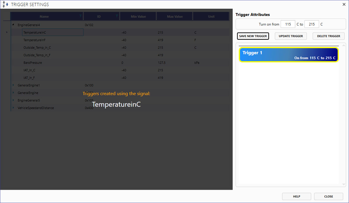
Triggers are currently only based on CAN messages. To create a trigger, select a signal and configure when the circuit will be ON based upon the signal.
With the example below, a trigger has been created using the "TemperatureinC" signal from the MicroPlex Demo .sym file. This means the signal is being monitored by the controller, which will turn the output pin in the circuit ON when the temperature signal is between 115 °C and 215 °C.

