Using Components
Placing Components On The Workspace
Click on the desired component in the Components pane, drag it onto the workspace, and then release the mouse to place a component on the workspace. If you attempt to place a component where there are not sufficient available sockets, the component will not be placed.
Right-Click Context Menu
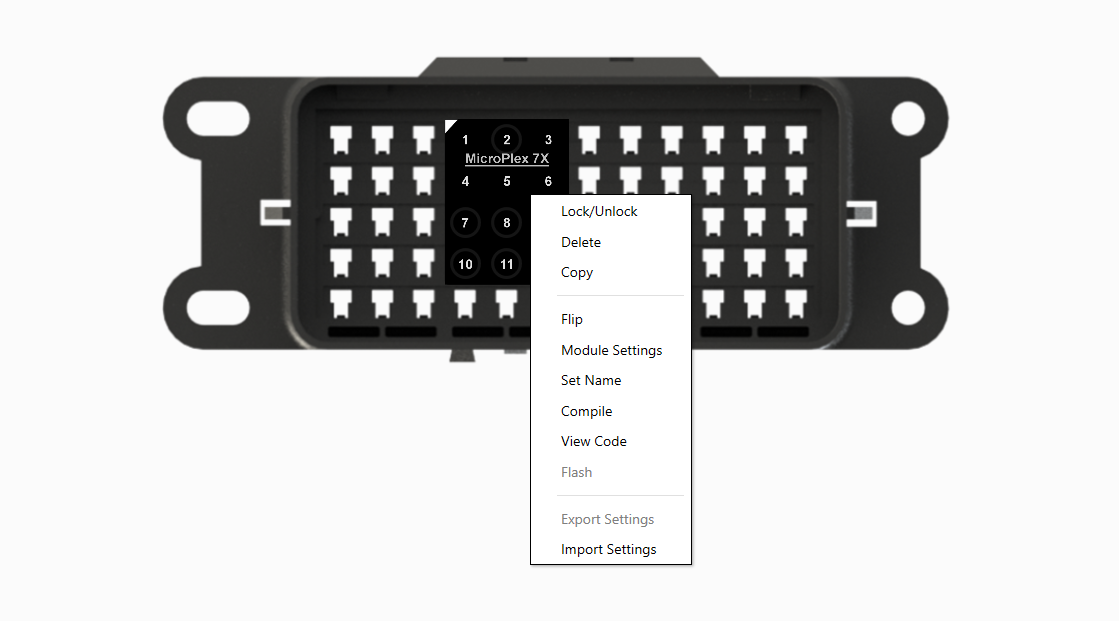
When you right-click on a component in the workspace, you will be shown a context menu with options for the component. Some options are only available for MicroPlex controllers.

Lock/Unlock
Lock or unlock the selected component. Moving, deletion, and changes in logic for the component and its pins are disabled while it is locked.
Delete
Delete the selected component. If there is logic created on this component, you will be asked to confirm the deletion.
Copy
Copy the selected component. Right-click in an open area on the workspace to paste the component. You will be prompted to assign a name to the newly created component. When copying a MicroPlex controller, this feature will copy all of the data in the CAN Settings window from the original MicroPlex controller but will not save any triggers. If the space selected for the paste action does not have enough space for the component, it will not be pasted.
Flip
Rotate the component 180 degrees. Components cannot be rotated 90 degrees as the terminals in most fuse and relay boxes do not support this rotation.
Module Settings
Open the workspace that contains the CAN settings, digital IOs, analog inputs, PWM outputs, and EEPROMs for this component. More...
Set Name
Set a custom name for the selected controller. This is useful for referencing back to the compiled code from the controller later.
Compile
Take all user created triggers and custom code and compile it. Once finished, you will get a response informing you if your compilation was sucessful or not. For every change made to the program for the controller, you will need to take this action to compile the new instructions for the controller. A detailed log of the compile process is stored in the log.txt file, which can be found using the View Code menu option.
View Code
The View Code option opens the folder containing the module's code and compile results. This code is what compiles after clicking the compile option. This folder also contains the compile result, a .s19 flash file and a detailed compile report log.txt.
Flash
Open the built-in controller flash tool. This will select the most recently compiled program and attempt to find the controller via the MicroPlex Programmer or supported flash tools. Different flash tools can be selected globally in the settings pane of the application. More...
Export Settings
Similar to the Copy function, you can export the CAN Settings of the selected controller to a file for use later.
Import Settings
Import a previously exported settings file into the selected controller.
Customizing Components
MicroPlex Lab automatically defaults to the newest revisions of the MicroPlex controllers and the most commonly used amperage of fuse, allowing you to jump right into your project with minimal setup. In the rare instances where modification is needed, you do have the option of customizing both the controllers and fuses to meet the requirements of your individual project.
Selecting MicroPlex Revision
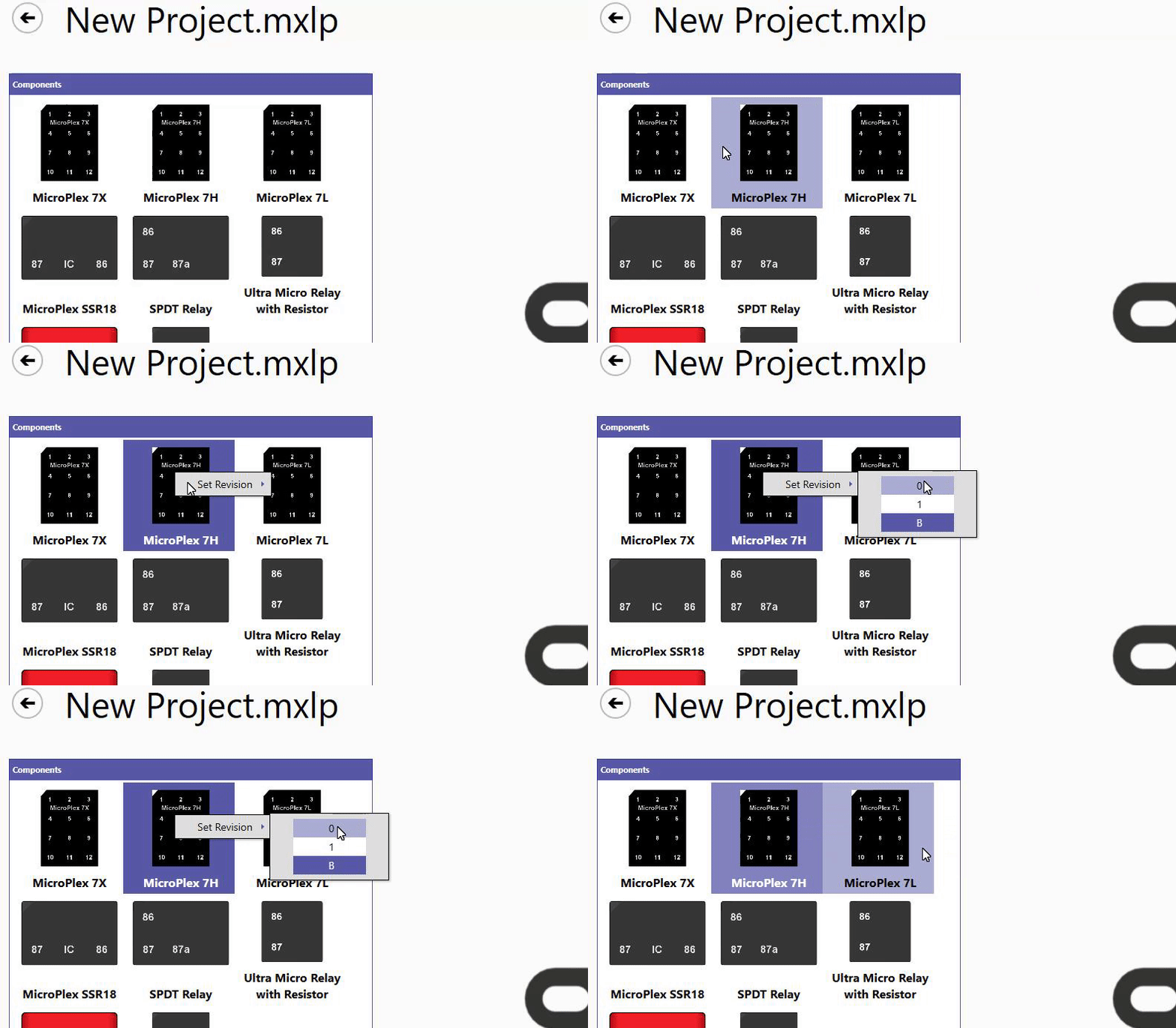
To ensure that you are using the MicroPlex revision that matches your hardware, right-click the desired MicroPlex in the Components pane. A menu will appear, allowing you to choose from any available revisions of the MicroPlex.

Selecting Fuse Amperage
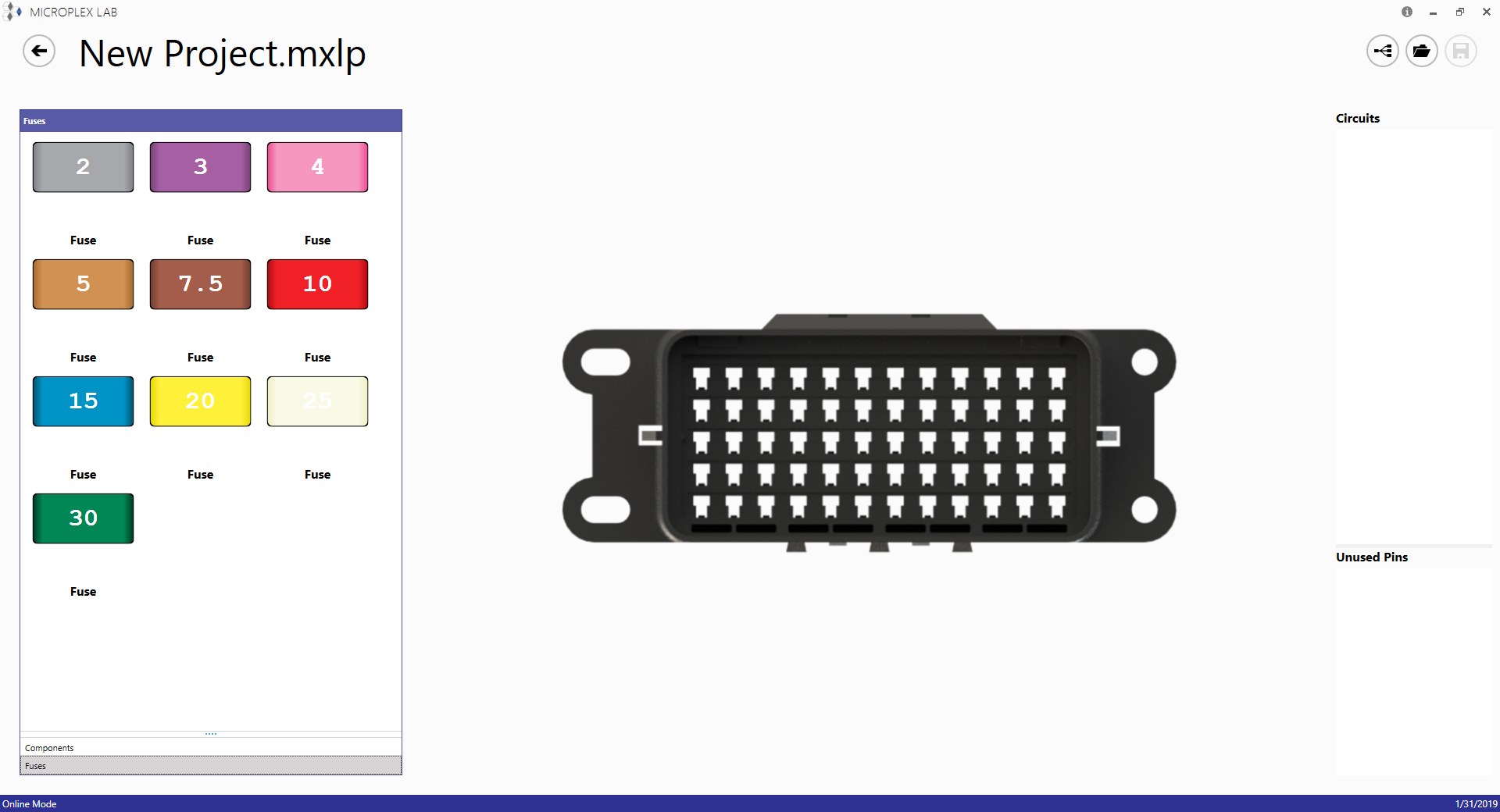
The default amperage of fuses in MicroPlex Lab is 10 amps. To use different amperages, click on the Fuses tab at the bottom of the Components pane. This will display all available fuse amperages.

Setting Default Amperage
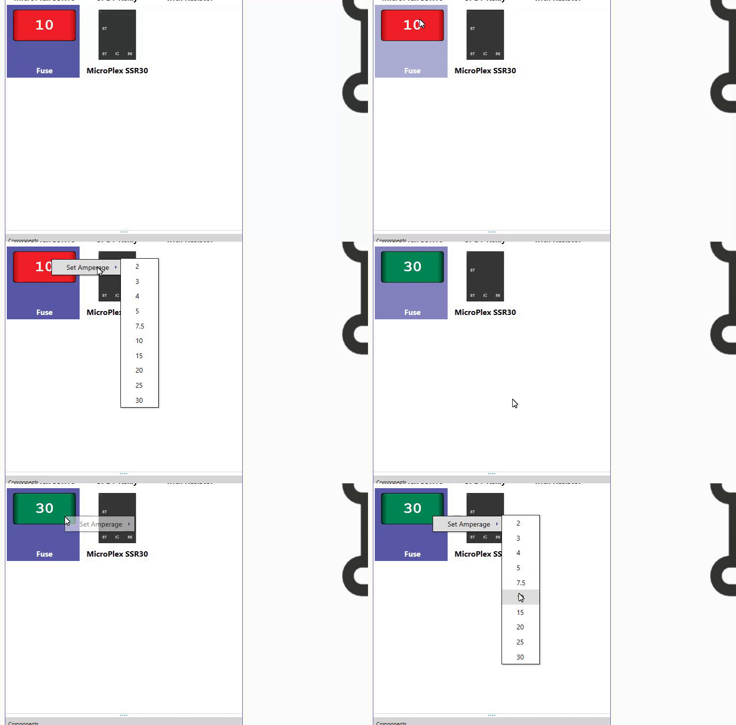
To change the default amperage for fuses, right-click on the fuse on the Components pane and select the desired amperage.

